A527 / T527
Octa Cortex-A55 SoC with a 2 TOPS NPU (T527 and MR527 only), HDMI 2.0, eDP, dual LVDS and dual GbE MACs, but one PCIe 2.1 lane shared with USB 3.1 and a 4 GB DRAM ceiling; the T527 is the -40 to 85 C industrial grade with 2x CAN.
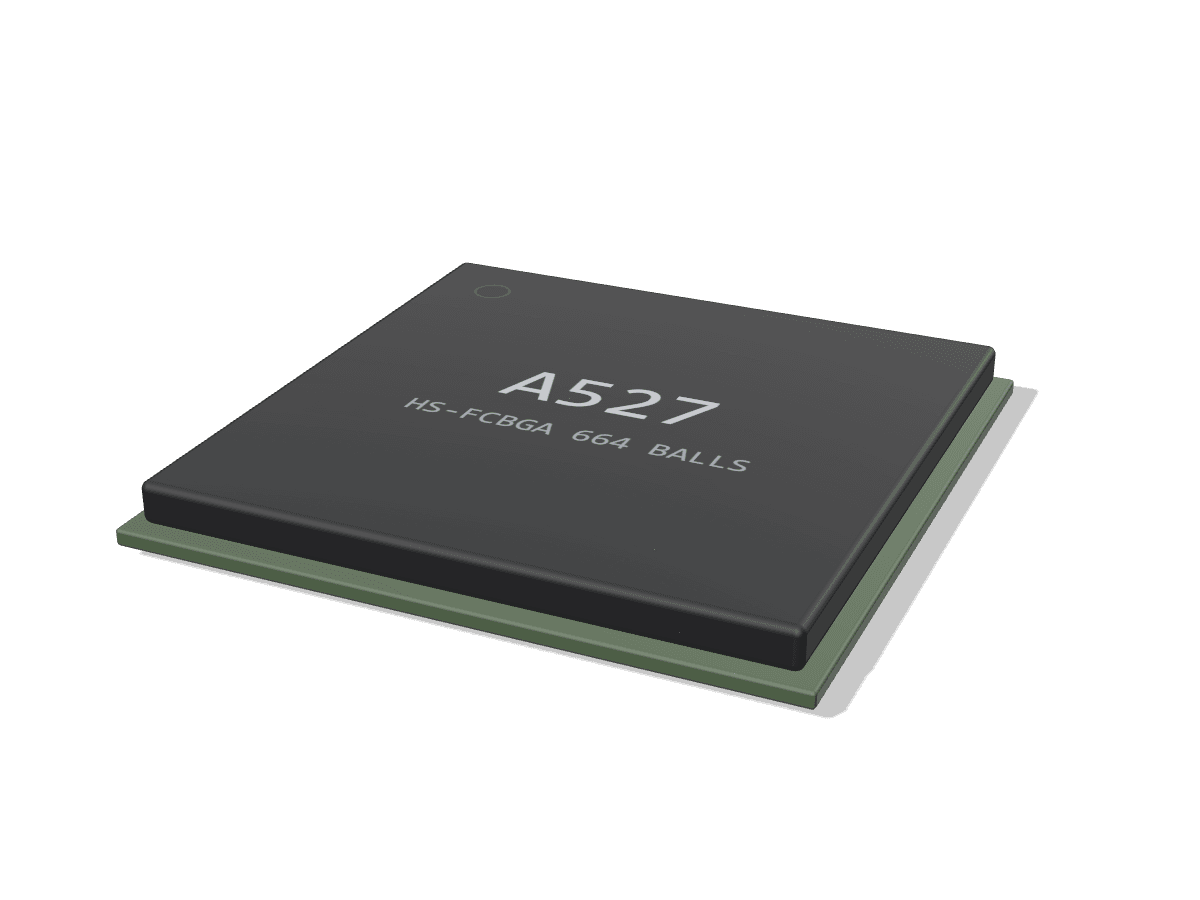
- CPU
- 4x A55 up to 2.0 GHz + 4x A55 (8 cores)
- GPU
- Mali-G57 MC1
- NPU
- 2 TOPS (T527M02, MR527); none on A523/A527
- Video
- 4K60 H.265/VP9 dec, 4K25 H.264 enc
- PCIe
- PCIe 2.1 x1 (shared with USB 3.1)
What the A527 / T527 is for
Right for
- Industrial HMI and kiosk boards that need many panel types: HDMI 2.0, eDP 1.3, 4+4-lane MIPI DSI, two dual-link LVDS and two RGB ports, with dual display from the same chip (T527 and A527)
- Gateways and controllers needing two Ethernet ports on MACs: two RGMII GbE controllers on T527 and A527, plus 2x CAN on T527
- Wide-temperature products: T527 is rated -40 to 85 C ambient, against -25 to 75 C for A527 and A523
- Light edge-AI vision: 2 TOPS NPU on T527M02 and MR527 with up to four MIPI CSI cameras (2+2+2+2 lanes) and an 8 MP ISP
- Designs that want an open boot chain: mainline U-Boot initializes DRAM with open source code (no DRAM blob) since v2025.10
Wrong for
- Anything needing more than 4 GB of DRAM: every datasheet caps the 32-bit controller at 4 GB
- NVMe and USB 3 together: the single PCIe 2.1 x1 lane and the USB 3.1 port share one combo PHY, so boards mux one or the other
- Hardware H.264 or H.265 encode above 4K25, or HEVC encode at all: the encoder is H.264 and JPEG only
- Products that need the display, video engine, USB 3 or PCIe on mainline Linux today: none of these are upstream as of 7.3-rc7
- Heavy AI workloads: 2 TOPS is the only NPU option, and A523 and A527 have none
Cost and constraints
- Three packages on one die: A523 FCCSP 522 balls 15 x 15 mm, A527 FCCSP or ED-FCCSP 660 balls 17 x 17 mm, T527 HS-FCBGA 664 balls 17 x 17 mm; all 0.5 mm pitch, 0.3 mm balls, so plan HDI fanout
- Every public board checked uses two X-Powers PMICs: AXP717 (main rails, charger) plus AXP323 for the big-cluster CPU rail
- Vendor software is Allwinner's Tina Linux and Android BSPs; Allwinner publishes its AIoT Linux SDK and documents on GitLab (Tina5.0_AIOT), and board vendors ship their own BSPs
- 4K60 H.265 decode: the T527 datasheet says it needs additional design per Allwinner's hardware design guide, and the A523 datasheet rates its 1.8 GHz grade at 4K30 (A527 datasheet V0.93 did the same for A527M; V0.96 drops the per-grade column)
Inside the A527 / T527
Drawn by Groundplane from the datasheet v0.95. Not Allwinner artwork.
- 32-bit DDR3/DDR4/LPDDR4/4X
- eMMC 5.1 HS400
- SD 3.0, SDIO 3.0
- Octal SPI NOR/NAND
- 8-bit raw NAND
- 4x Cortex-A55 big, up to 1.8/2.0 GHz
- 4x Cortex-A55 LITTLE
- 1 MB L3, 128/64 KB L2 per core
- RISC-V E906 MCU, 200 MHz
- Mali-G57 MC1
- G2D 2D engine
- 2 TOPS, 512 KB buffer (T527M02)
- 4K60 H.265/VP9 decoder
- 4K30 H.264 decoder
- 4K25 H.264 encoder
- JPEG/MJPEG, de-interlacer
- 32-bit DRAM, 4 CS, 4 GB max
- DDR3/DDR4/LPDDR3/LPDDR4/4X
- Display engine, 2 outputs
- HDMI 2.0 TX, eDP 1.3
- MIPI DSI 4+4, LVDS x2, RGB x2
- MIPI CSI-2, up to 4 ports
- 16-bit parallel CSI
- 8 MP ISP, 2F-WDR
- Crypto engine, TRNG
- 4 Kbit eFuse, secure BROM
- TrustZone (SMC, SPC)
- HiFi4 DSP (T527)
- Audio codec, 2 DAC, 3 ADC
- 5 thermal sensors
- Two 16-ch DMA, IOMMU
- PCIe 2.1 x1 or USB 3.1
- USB 2.0 DRD (FEL)
- USB 2.0 host
- 2x GbE MAC (RGMII/RMII)
- 2x CAN (T527)
- HDMI 2.0, eDP 1.3
- MIPI DSI 4+4, 2x LVDS, 2x RGB
- MIPI CSI 4+4 lanes, DVP
- I2S x4, DMIC, S/PDIF
- UART x10, TWI x9, SPI x4, PWM x30
Read from the documents
Each value names the document it was read from.
| CPU | Octa Cortex-A55 in a DynamIQ big.LITTLE configuration, 32 KB L1 I/D per core, 64 KB L2 per LITTLE core, 128 KB L2 per big core, 1 MB L3; plus a RISC-V core up to 200 MHz | Datasheet V0.95, 3.1, Figure 4-1 |
|---|---|---|
| CPU clock | T527: up to 1.8 GHz. A527H000000H, A527H00X000H and A523H00X0000: 2.0 GHz; A527M and A523M: 1.8 GHz | Datasheet V0.95, 3.1; A527 V0.96 and A523 Table 2-1 |
| GPU | Arm Mali-G57 MC1; OpenGL ES 3.2/2.0/1.1, Vulkan 1.1/1.2/1.3, OpenCL 2.2 | Datasheet V0.95, 3.3 |
| NPU | 2 TOPS with a 512 KB internal buffer on T527M02X0DCH; not supported on T527M00X0DCH; no NPU in the A527 or A523 datasheets | Datasheet V0.95, 3.2, Table 2-1 |
| Video decode | H.265 Main/Main10 and VP9 Profile 0/2 up to 4096x2304 at 60 fps (10-bit); H.264 BP/MP/HP up to 4096x2304 at 30 fps. A527 datasheet V0.96 adds 7680x4320 at 24 fps for H.265 and VP9 and no longer limits the 1.8 GHz grade; the A523 datasheet still rates its 1.8 GHz grade at 4K30 | Datasheet V0.95, 3.6.4.1; A527 3.4.4.1; A523 Table 2-1 |
| Video encode | H.264 BP/MP/HP up to 4K at 25 fps (max 4096x4096), 8 ROIs; MJPEG up to 4K at 15 fps; JPEG up to 8192x8192 | Datasheet V0.95, 3.6.4.2 |
| ISP | One ISP, 3264x4224 online, 8 MP at 30 fps with 2-frame WDR, 2D/3D noise reduction, 3A statistics; four VIPP scaler outputs | Datasheet V0.95, 3.8.1, 3.8.2 |
| Memory | 32-bit DDR3, DDR3L, DDR4, LPDDR3, LPDDR4, LPDDR4X; up to 4 GB; 4 chip selects for LPDDR; clock up to 1066 MHz (DDR3/DDR3L/LPDDR3) and 1200 MHz (DDR4/LPDDR4/LPDDR4X) | Datasheet V0.95, 3.5.3 |
| Storage | eMMC 5.1 with HS400/HS200 (SMHC2), SD 3.0 (SMHC0), SDIO 3.0 (SMHC1), 8-bit raw NAND with up to 80-bit/1 KB ECC, SPI NOR and SPI NAND, octal SPI flash controller (150 MHz STR, 100 MHz DTR) | Datasheet V0.95, 3.5.1, 3.5.2, 3.5.4, 3.12.11 |
| Display | HDMI 2.0 TX up to 4096x2160 at 60 with HDCP 1.4; eDP 1.3 up to 2.5K60 or 4K30 (4 lanes, 2.7 Gbps); 4+4-lane MIPI DSI up to 2560x1600 at 60 or 4096x2160 at 45 (single 4-lane link 1920x1200 at 60); two dual-link LVDS up to 1080p60; two RGB, one up to 1080p60 and one (TCON_LCD2) up to 720p60; display engine with two outputs. A523: no HDMI, one dual-link LVDS and one RGB | Datasheet V0.95, 3.6.1, 3.7; A523 features page |
| Camera | MIPI CSI-2 V1.1 as 4+4, 4+2+2 or 2+2+2+2 lanes at 2.0 Gbps per lane, 8 MP at 30 fps; 8/10/12/16-bit parallel CSI with BT.656 and BT.1120 | Datasheet V0.95, 3.8.3, 3.8.4 |
| PCIe | 1x PCIe 2.1 x1 (Gen1/Gen2), root complex only; shares one combo PHY with the USB 3.1 controller | Datasheet V0.95, 3.12.8 |
| USB | 1x USB 3.1 Gen1 DRD (5 Gbps) on the PCIe combo PHY, 1x USB 2.0 DRD (USB0, also the FEL download port), 1x USB 2.0 host | Datasheet V0.95, 3.12.6 to 3.12.8 |
| Ethernet | Two MACs on T527 and A527: GMAC0 (10/100/1000, RGMII/RMII) and GMAC1 "GMAC200" (10/100/1000, RGMII/RMII, IEEE 1588, TCP/IP checksum offload). A523 has GMAC0 only | Datasheet V0.95, 3.12.1, 3.12.2; A523 features page |
| Audio | On-chip codec with 2 DACs (to 192 kHz) and 3 ADCs, headphone and two differential line outputs, 3 differential mic inputs; 4x I2S/PCM with TDM, 8-mic DMIC, S/PDIF in and out; HiFi4 DSP on T527 only | Datasheet V0.95, 3.4, 3.10 |
| Security | Crypto engine: AES, DES, 3DES, SM4, SHA-1/2, SM3, HMAC, RSA up to 4096, ECC, SM2, TRNG; 4 Kbit eFuse; secure boot BROM; TrustZone memory and peripheral control | Datasheet V0.95, 3.11 |
| Other I/O | 10x UART, 9x TWI, 4x SPI, 30-ch PWM, 24-ch GPADC (4-ch on A523), 2-ch LRADC, 2x CIR RX and 1x CIR TX, LEDC; 2x CAN on T527 only | Datasheet V0.95, 3.12, Figure 4-1 |
| Package | T527: HS-FCBGA 664 balls, 17 x 17 mm, 1.844 mm max height, 0.5 mm pitch, 0.3 mm balls. A527: FCCSP or ED-FCCSP 660 balls, 17 x 17 mm. A523: FCCSP 522 balls, 15 x 15 mm | Datasheet V0.95, 3.13; A527 and A523 cover pages |
| Temperature | T527: ambient -40 to 85 C, Tj -40 to 115 C (125 C destructive). A527 and A523: ambient -25 to 75 C, Tj -25 to 115 C | Datasheet V0.95, Tables 7-1, 7-2 |
| Thermal | T527 package: theta-JA 19.27, theta-JB 6.48, theta-JC 0.2 C/W (JEDEC 4-layer 114.3 x 76.2 mm board, still air); five on-chip thermal sensors on two controllers. A527: theta-JA 21.76 (ED-FCCSP) or 22.13 C/W (FCCSP) | Datasheet V0.95, Table 7-3, 3.9.9; A527 Tables 7-3, 7-4 |
Variants
| T527 | Industrial grade, HS-FCBGA 664 balls, 17 x 17 mm, -40 to 85 C. Up to 1.8 GHz. Adds a HiFi4 audio DSP and 2x CAN over the A527. T527M02X0DCH has the 2 TOPS NPU; T527M00X0DCH does not. linux-sunxi also lists H02X0DCH and H00X0DCH 2.0 GHz codes that are not in datasheet V0.91. | Datasheet V0.95 |
|---|---|---|
| A527 | Consumer grade (-25 to 75 C), 660 balls, 17 x 17 mm, in FCCSP (A527H000000H, A527M000000H) or ED-FCCSP (A527H00X000H, A527M00X000H). Same display set as T527 including HDMI 2.0 and the second GMAC, but no NPU, no DSP and no CAN. A527H runs at 2.0 GHz, A527M at 1.8 GHz. Datasheet V0.93 rated the 1.8 GHz grade at 4K30 H.265/VP9; V0.96 drops that column and lists 4K60 (8K24) decode for the series. | Datasheet V0.96 |
| A523 | Tablet part in a smaller FCCSP 522-ball, 15 x 15 mm package: one GMAC, no HDMI, one dual-link LVDS and one RGB, 4-ch GPADC, no NPU. A523H00X0000 at 2.0 GHz (4K60 decode), A523M00X0000 at 1.8 GHz (4K30). -25 to 75 C. Not pin compatible with A527/T527. | Datasheet V1.4 |
| MR527 | Robotics part: Allwinner lists octa A55 up to 1.8 GHz, 2 TOPS INT8 NPU, H.264 4K25 encode, one GMAC, 203 GPIOs and no display or video decoder rows. linux-sunxi lists it as M02X0D00 on the same die. No MR527 datasheet was found. | Other |
| H728 | Same sun55iw3 die per linux-sunxi, used in TV boxes; mainline has a device tree for the X96Q Pro+ (sun55i-h728-x96qpro+). No Allwinner page or datasheet was found. | Other |
What to watch when you design with it
Power and PMIC
Every public design checked pairs two X-Powers PMICs. The mainline device trees for Avaota A1, Orange Pi 4A and Cubie A5E describe an AXP717 plus an AXP323; the Boardcon CMT527 and Ebyte ECK32-T527B manuals name AXP717B plus AXP323, and the Industio IDO-SOM2708-S1 spec sheet names AXP717B. On Avaota A1 the AXP717 DCDC1 feeds the LITTLE cluster (vdd-cpul), DCDC2 the GPU and system rail at 0.92 V, DCDC3 DRAM at 1.16 V and DCDC4 the 3.3 V I/O; the AXP323 runs DCDC1 and DCDC2 as one polyphase rail for the big cluster (vdd-cpub) and DCDC3 at 0.9 V for vdd-dnr. Walnut Pi's bootloader initializes an AXP2202 and an AXP1530, which linux-sunxi describes as the OEM name for AXP717B/C and a member of the AXP313A/323 family. The AXP323 datasheet is public on MT-System, an Allwinner distributor, and Allwinner publishes the AXP717B datasheet (QFN-52, 6 x 6 mm, 4 bucks: DCDC1 0.5 to 1.54 V at 4 A, DCDC2 0.5 to 3.4 V at 3 A, DCDC3 0.5 to 1.84 V at 1.5 A, DCDC4 1.0 to 3.4 V at 3 A, plus 14 LDOs) with the T527 documents.
Sources: Other V3, Other V1.0, PMIC V1.1, PMIC V1.0, github.com, Other
Power-up sequence
The T527 datasheet (6.13.1) sets four ordering rules: VCC-LVDS0 before VCC-PD, VCC-MCSI before a 3.3 V VCC-PK (no rule for 1.8 V VCC-PK), VCC-EFUSE after VDD-SYS, and VCC-LVDS1 before VCC-PJ. A step starts only once the previous rails are within 90 to 110% of nominal, and rails in the same step must settle within 1 ms of each other. Hold RESET low until every rail except the 24 MHz clock has been stable for at least 6 ms; the 24 MHz oscillator must be stable within 4 ms after reset is stable.
Sources: Datasheet V0.95
DDR
One 32-bit controller with four chip selects, 4 GB maximum, DDR3, DDR3L, DDR4, LPDDR3, LPDDR4 or LPDDR4X. Every public board and module checked uses LPDDR4 or LPDDR4X, from 1 GB (Avaota A1, Cubie A5E, Walnut Pi) to 4 GB. Mainline U-Boot carries an open-source DRAM init for this die (dram_sun55i_a523.c, 2025-07-27), so a mainline boot chain needs no DRAM blob. No Allwinner DRAM layout guide is linked here; the closest public reference layout is the Avaota A1 board itself, published under CERN-OHL-S-2.0.
Sources: Datasheet V0.95, github.com, Board schematic v1.7
High-speed interfaces
The single PCIe 2.1 x1 lane and the USB 3.1 Gen1 port share one combo PHY, so a board offers NVMe or USB 3, not both at once. Radxa's Cubie A5E switches between its M.2 slot and USB 3 with a GPIO (linux-sunxi); Walnut Pi 2B and CM2 mux the PCIe FFC with USB 3.0. Forlinx's UP4 module does not bring PCIe out at all. Two RGMII MACs are available on T527 and A527 only; the A523 has one. The datasheet says 4K60 decode on T527 needs additional design work per Allwinner's hardware design guide, which is not public.
Sources: Datasheet V0.95, Other, Other, Datasheet V1.4
Boot and FEL
The boot ROM boots from SD, eMMC, raw NAND, SPI NOR or SPI NAND. A low FEL pin sends it into the mandatory upgrade path (USB FEL on USB0), so bring FEL out as a button. When the eFuse BOOT_MODE bit is 0, a resistor divider on the GPADC0 pin picks the boot order from a table in which the SD card is always tried first, followed by NAND, eMMC (user or boot area first), SPI NOR or SPI NAND; if the chosen medium fails the ROM falls back through eMMC user, eMMC boot, NAND, SPI NOR and SPI NAND. With BOOT_MODE fused to 1, three eFuse boot-select groups fix the order instead. Because SD comes first, a bootable card in the slot always wins over eMMC.
Sources: TRM V0.94
Gotchas
A523 is a different package (522 balls, 15 x 15 mm) and is not pin compatible with A527 or T527. Two LGA modules share a 45 x 43 mm, 381-pad outline (MYIR MYC-LT527 and Ebyte ECK32-T527B) but no vendor states they are interchangeable. Vendor clock claims differ from the datasheet: Kickpi advertises its T527 board at up to 2.0 GHz, while T527 datasheet V0.91 lists 1.8 GHz and the 2.0 GHz T527H codes appear only on linux-sunxi and in MYIR's ordering table. The mainline NPU node uses the generic etnaviv binding and its commit notes it is unclear whether A523 and A527 have the NPU fused off.
Sources: Datasheet V1.4, Other, Other V1.0, Datasheet V0.95, Other
Layout guides for the A527 / T527's interfaces
Public layout guidance for each interface this chip has, from vendors who publish it, plus our calculators.
LPDDR4
Point-to-point routing; TI notes that on-die termination on both ends means no board termination is needed. Byte lanes length-matched to their strobe and command/address matched to the clock, all over a solid reference plane. Impedance targets differ by vendor: TI AM62x and ADI EE-480 use 40 ohm single-ended and 80 ohm differential, Synaptics SL1680 uses 50 and 85 ohm, AMD Versal 45 and 82 ohm. Use the SoC vendor's own target and simulate.
- AM62x, AM62Lx DDR Board Design and Layout GuidelinesTexas Instruments, SPRAD06, C, 2025
- AM62Ax, AM62Px, AM62Dx LPDDR4 Board Design and Layout GuidelinesTexas Instruments, SPRAD66, B, 2024
- ADSP-2184x/ADSP-SC84x LPDDR4 Board Design GuidelinesAnalog Devices, EE-480, 1, 2026
- SL1680 General PCB Design and LPDDR4 & LPDDR4(x) Interface Layout GuidelinesSynaptics, PN 506-001390-01, E
- DDR length matching calculatorGroundplane calculator
LPDDR4X
Same topology and matching discipline as LPDDR4, with a lower I/O voltage, so routing rules are usually published for both together. Synaptics SL1680 gives 50 ohm single-ended and 85 ohm differential for LPDDR4 and LPDDR4X; AMD Versal gives 45 and 82 ohm. Check the SoC vendor target before fixing the stackup.
- SL1680 General PCB Design and LPDDR4 & LPDDR4(x) Interface Layout GuidelinesSynaptics, PN 506-001390-01, E
- SL1640 General PCB Design and DDR4 & LPDDR4(x) Interface Layout GuidelinesSynaptics, PN 506-001529-01, D
- Versal Adaptive SoC PCB Design User Guide: PCB Routing Guidelines for LPDDR4/4x InterfacesAMD, UG863, 1.12, 2026
- DDR length matching calculatorGroundplane calculator
DDR4
DDR4 uses pseudo open-drain data signaling and needs a VPP supply, with command/address routed fly-by or as a balanced tree depending on device count. TI AM62x uses 40 ohm single-ended and 80 ohm differential; AMD Versal uses 50 and 90 ohm, relaxed under the BGA. Match data to strobe per byte and command/address to clock.
- AM62x, AM62Lx DDR Board Design and Layout GuidelinesTexas Instruments, SPRAD06, C, 2025
- Versal Adaptive SoC PCB Design User Guide: PCB Routing Guidelines for DDR4 InterfacesAMD, UG863, 1.12, 2026
- SL1640 General PCB Design and DDR4 & LPDDR4(x) Interface Layout GuidelinesSynaptics, PN 506-001529-01, D
- PCB Design Guidelines (HSSI, EMIF, MIPI, True Differential, PDN) User Guide: Agilex 5 FPGAs and SoCsAltera, 821801, 2026
- DDR length matching calculatorGroundplane calculator
- Via current calculatorGroundplane calculator
DDR3 / DDR3L
Fly-by command/address with termination at the end of the chain, point-to-point data lanes matched to their strobe, and a clean VREF. ST recommends 55 ohm single-ended and 100 ohm differential for DDR3 and DDR3L on STM32MP1 boards, and shows that a 4-layer board is possible with strict layer allocation.
- STM32MP1 Series DDR memory routing guidelinesSTMicroelectronics, AN5122, 3, 2019
- DDR3 Design Requirements for KeyStone DevicesTexas Instruments, SPRABI1, D, 2022
- SL2610 General PCB Design and DDR3L/DDR4 & LPDDR4(x) Interface Layout GuidelinesSynaptics, PN 506-001629-01, A, 2025
- DDR length matching calculatorGroundplane calculator
LPDDR3
Point-to-point and normally unterminated, with command/address matched to the clock and each byte matched to its strobe. ST gives the same targets for LPDDR3 as for DDR3: 55 ohm single-ended and 100 ohm differential. Few current public guides cover LPDDR3, so treat the SoC vendor's reference layout as the stronger source.
- STM32MP1 Series DDR memory routing guidelinesSTMicroelectronics, AN5122, 3, 2019
- DDR length matching calculatorGroundplane calculator
eMMC
A single-ended bus: CLK, CMD, DAT0 to DAT7 and, for HS400, the data strobe. TI and Synaptics both route it at 50 ohm single-ended, match the group, and keep stubs short; Synaptics places a 22 or 33 ohm series resistor on CLK and STRB. At HS400 TI also checks the eMMC I/O supply impedance, not just the traces.
- AM62Px eMMC HS400 Board Design and Simulation GuidelinesTexas Instruments, SPRADP5, A, 2026
- Astra Machina Foundation Series eMMC ConfigurationSynaptics, PN 506-001594-01, D
- i.MX28 Layout and Design GuidelinesNXP (Freescale), AN4215, 0, 2010
SD card / SDIO
Single-ended CLK, CMD and four data lines over a solid ground plane, at constant trace width and matched length. NXP asks for clock-to-neighbor spacing greater than twice the trace height above the plane and 1.5 times for data and CMD, with 45 degree bends. UHS modes switch the I/O to 1.8 V, so a level translator often sits next to the socket.
- NVT4557/NVT4558/NVT4858 voltage-level translator layout guidelineNXP, AN13158, 1.1, 2022
- i.MX28 Layout and Design GuidelinesNXP (Freescale), AN4215, 0, 2010
- SD Physical Layer Simplified SpecificationSD Association, 9.10, 2023
PCIe
AC-coupled differential lanes routed with no stubs, minimal vias and back-drilled or blind vias where speed demands, with lane-to-lane skew handled by the receiver. Targets differ by guide: TI Jacinto 7 uses 85 ohm differential for lanes and 100 ohm for the reference clock, while TI's earlier SoC guide tabulates 100 ohm and, for some devices, 95 ohm. Match the target to your connector and stackup.
- Jacinto7 AM6x, TDA4x, and DRA8x High-Speed Interface Design GuidelinesTexas Instruments, SPRACP4, A, 2024
- High-Speed Interface Layout GuidelinesTexas Instruments, SPRAAR7, J, 2023
USB 3.x
SuperSpeed TX and RX pairs are routed at 90 ohm differential in all three TI guides (SPRAAR7 lists 95 ohm for some devices), with AC coupling capacitors on TX, symmetric pad and via placement, and matched via counts within each pair. Keep the pairs away from the USB 2.0 pair and other aggressors, and place ESD at the connector.
- High-Speed Layout Guidelines for Signal Conditioners and USB HubsTexas Instruments, SLLA414, A, 2026
- Jacinto7 AM6x, TDA4x, and DRA8x High-Speed Interface Design GuidelinesTexas Instruments, SPRACP4, A, 2024
- High-Speed Interface Layout GuidelinesTexas Instruments, SPRAAR7, J, 2023
USB 2.0
One D+/D- pair at 90 ohm differential, routed in parallel for its whole length with minimal deviations at the connector and package. NXP keeps clocks and periodic signals at least 50 mils away and other signals at least 20 mils away from the pair.
- High-Speed Layout Guidelines for Signal Conditioners and USB HubsTexas Instruments, SLLA414, A, 2026
- High-Speed Interface Layout GuidelinesTexas Instruments, SPRAAR7, J, 2023
- i.MX28 Layout and Design GuidelinesNXP (Freescale), AN4215, 0, 2010
HDMI
Four TMDS pairs (three data, one clock) at 100 ohm differential, as both TI guides state, with tight intra-pair matching and as few vias as possible between the SoC and the connector. HDMI also needs 5 V supply switching, DDC and CEC level handling, hot-plug detect and ESD at the connector.
- High-Speed Layout Guidelines for Signal Conditioners and USB HubsTexas Instruments, SLLA414, A, 2026
- High-Speed Interface Layout GuidelinesTexas Instruments, SPRAAR7, J, 2023
- TPD12S016 PCB Layout Guidelines for HDMI ESDTexas Instruments, SLLA324, 2012
DisplayPort / eDP
Main-link lanes are routed at 100 ohm differential in both TI guides, with no stubs and few vias; TI Jacinto 7 allows 2 vias per trace. When DisplayPort shares a USB-C connector through alt mode, the lanes run through the Type-C mux and the SuperSpeed rules apply to the shared path.
- High-Speed Layout Guidelines for Signal Conditioners and USB HubsTexas Instruments, SLLA414, A, 2026
- Jacinto7 AM6x, TDA4x, and DRA8x High-Speed Interface Design GuidelinesTexas Instruments, SPRACP4, A, 2024
MIPI DSI
MIPI D-PHY clock and data lanes are routed as 100 ohm differential pairs over a solid reference; TI Jacinto 7 allows no stubs, 2 vias per trace and 40 ps lane-to-lane skew. Connectors and flex cables to the panel are usually the largest discontinuity, so keep the board segment short and clean.
- Jacinto7 AM6x, TDA4x, and DRA8x High-Speed Interface Design GuidelinesTexas Instruments, SPRACP4, A, 2024
- PCB Design Guidelines (HSSI, EMIF, MIPI, True Differential, PDN) User Guide: Agilex 5 FPGAs and SoCsAltera, 821801, 2026
MIPI CSI-2
Same D-PHY rules as DSI: 100 ohm differential lanes in both TI guides, with lane-to-lane skew bounded (40 ps in TI Jacinto 7). Size the lane count and lane rate from the sensor's output format before routing.
- Jacinto7 AM6x, TDA4x, and DRA8x High-Speed Interface Design GuidelinesTexas Instruments, SPRACP4, A, 2024
- High-Speed Interface Layout GuidelinesTexas Instruments, SPRAAR7, J, 2023
- PCB Design Guidelines (HSSI, EMIF, MIPI, True Differential, PDN) User Guide: Agilex 5 FPGAs and SoCsAltera, 821801, 2026
- MIPI CSI-2 bandwidth calculatorGroundplane calculator
LVDS
Tightly coupled differential pairs terminated at the receiver in 100 ohm, with TI's EMI guide asking for 100 ohm differential traces within 5 percent. Keep pairs matched and away from other aggressors, and avoid stubs and reference plane gaps along the route to the panel connector.
- LVDS Owner's Manual: Including High-Speed CML and Signal ConditioningTexas Instruments, SNLA187, 4th edition, 2008
- High-Speed Layout Guidelines for Reducing EMI for LVDS SerDes DesignsTexas Instruments, SNLA302, 2018
- LVDS SerDes Gen I PCB and Interconnect Design-In GuidelinesTexas Instruments, SNLA008, A, 2018
Ethernet (RGMII / RMII)
TI routes MAC-to-PHY (MII family) traces at 50 ohm single-ended, under 6 inches, matched within 20 mils for gigabit, and the PHY-side MDI pairs at 100 ohm differential. RGMII also needs a 1.5 to 2.0 ns clock-to-data delay, added on the board or inside the MAC or PHY (RGMII-ID); decide which before layout so it is not applied twice.
- Ethernet PHY PCB Design Layout ChecklistTexas Instruments, SNLA387, 2021
- PCB Design Guideline for RGMII InterfaceRenesas, R01AN6272EJ0141, 1.41, 2026
- i.MX28 Layout and Design GuidelinesNXP (Freescale), AN4215, 0, 2010
Board-level design guides
Impedance and timing, power, thermal and ESD guidance that applies to any board around this chip.
Impedance and timing
Every high-speed interface on the board comes down to the same two numbers: the trace impedance your stackup actually gives, and the delay each trace adds. Set the stackup with your fab first, then route to its impedance table and match lengths in time, not millimeters, where the layers differ.
- High-Speed Interface Layout GuidelinesTexas Instruments, SPRAAR7, J, 2023
- PCB impedance calculatorGroundplane calculator
- PCB propagation delay calculatorGroundplane calculator
Power delivery
For each switching regulator, place and route the input capacitor first, keep the switching current loop small, and keep the switch node short. Give the SoC rails solid planes and decoupling at the balls, and size current-carrying copper and vias for the real load.
- Five steps to a great PCB layout for a step-down converterTexas Instruments, SLYT614, 2015
- AN-1149 Layout Guidelines for Switching Power SuppliesTexas Instruments, SNVA021, C, 2013
- AN-1229 SIMPLE SWITCHER PCB Layout GuidelinesTexas Instruments, SNVA054, C, 2013
- Buck converter calculatorGroundplane calculator
- LDO power dissipation calculatorGroundplane calculator
- PCB trace width calculatorGroundplane calculator
- Via current calculatorGroundplane calculator
Thermal
Theta-JA is measured on a JEDEC test board that carries most of the heat, so it does not transfer directly to a product board; use it to compare packages and use the psi metrics for estimates. Thermal vias under the package, copper area and copper thickness move the most heat into the board.
- Semiconductor and IC Package Thermal MetricsTexas Instruments, SPRA953, D, 2024
- AN-2020 Thermal Design By Insight, Not HindsightTexas Instruments, SNVA419, C, 2013
- Heatsink thermal resistance calculatorGroundplane calculator
- LDO power dissipation calculatorGroundplane calculator
ESD protection
Place the TVS as close to the connector as design rules allow, route from the connector to the TVS with no stub, and keep the protected IC further from the TVS than the TVS is from the connector. Choose parts by clamping performance and by capacitance low enough for the interface speed.
- ESD Protection Layout GuideTexas Instruments, SLVA680, A, 2022
- Reading and Understanding an ESD Protection Data SheetTexas Instruments, SLLA305, A
- TPD12S016 PCB Layout Guidelines for HDMI ESDTexas Instruments, SLLA324, 2012
- PCB conductor spacing calculator (IPC-2221)Groundplane calculator
Allwinner's hardware design guide
Allwinner's hardware design guide, EVB reference schematics and DDR templates come from Allwinner or an authorized agent, usually under NDA, or through your SoM vendor. We do not link copies circulating elsewhere. The vendor schematics and open designs on the Boards tab are real, shipped layouts on the A527 / T527 and the best public reference.
BSP, mainline and toolkits
| Area | Status | Links |
|---|---|---|
| Vendor BSP kernel | Allwinner publishes its AIoT Linux SDK on GitLab (Tina5.0_AIOT, release v1.5.0 on 2026-07-15): a Linux 6.6.98 kernel with a sun55iw3p1 (A523/A527/T527) config and A523, A527 and T527 build targets. Board and module vendors ship Linux 5.15 BSPs: Forlinx 5.15.104 with Qt 5.12.5, MYIR 5.15 with U-Boot 2018.02, Boardcon 5.15.147, Orange Pi 5.15.147, Walnut Pi 5.15.147, Ebyte 5.15.147 with U-Boot 2018.07 and Buildroot 202205. AvaotaSBC keeps a public linux-5.15 branch, which Armbian uses for its legacy kernel on this family.Checked 2026-10-13 | |
| Mainline Linux | Basic SoC support from v6.15. v6.16 added sun55i-a523.dtsi with device trees for Cubie A5E (A527), Avaota A1 (T527) and X96Q Pro+ (H728); v6.17 the Orange Pi 4A and the Mali-G57 node for Panfrost; v6.18 the NPU node; v6.19 GMAC1, I2S, S/PDIF and DMA; v7.0 SPI; v7.1 LEDC; v7.2 GPADC; 7.3-rc IR. Not upstream as of 7.3-rc7: display and HDMI, the video engine, the USB 3/PCIe combo PHY, thermal and CPU DVFS.Checked 2026-10-13 | |
| NPU | The v6.18 device tree node (commit a1845487afd0, 2025-09-13) describes the NPU with the generic etnaviv "vivante,gc" binding; it reports a GC9000 rev 9003. Vendor BSPs carry Allwinner's own NPU stack, which is not public.Checked 2026-10-13 | |
| U-Boot | Mainline U-Boot supports the die with open-source DRAM init (2025-07-27) and defconfigs for avaota-a1, radxa-cubie-a5e and x96q_pro_plus (2025-07-27) and orangepi_4a (2025-10-27); linux-sunxi gives v2025.10-rc1 as the first release. Vendor BSPs use Allwinner's U-Boot 2018 fork.Checked 2026-10-13 | |
| TF-A | Upstream Trusted Firmware-A has no sun55i platform (plat/allwinner lists A64, H6, H616, R329 and A133 on 2026-10-13). Mainline builds use Jernej Skrabec's work-in-progress a523-v4 branch, last updated 2025-10-28.Checked 2026-10-13 | |
| Distributions | Armbian community builds for Cubie A5E (current 6.18) and Orange Pi 4A (edge 7.2). Radxa OS Debian 11 R7 (2026-04-30, marked pre-release) for Cubie A5E; Orange Pi Ubuntu jammy and Debian bookworm images v1.0.4 on 5.15.147; Walnut Pi Debian 12 images up to V1.8.0 (2026-09-17); AvaotaOS 0.3.0.4 Ubuntu noble images (2025-02-21).Checked 2026-10-13 | |
| Android | Android 13 BSP images from Forlinx, MYIR, Boardcon (kernel 5.15.119), Radxa, Orange Pi and Kickpi. Forlinx marks its 2 GB modules "Android not recommended".Checked 2026-10-13 | |
| Community | linux-sunxi documents the die, its variants and the upstreaming status, and mirrors the datasheets and user manual.Checked 2026-10-13 |
A527 / T527 system on modules
Any of these can sit on a carrier board we design.
| Module | Vendor | Connector | RAM | Design files | Price | Buy |
|---|---|---|---|---|---|---|
| FET527N-C | Forlinx | 4x 80-pin 0.5 mm board-to-board, 2.0 mm mated height | 2 or 4 GB LPDDR4 (FET527-C without NPU adds 1 GB) | Product brief public; schematic, PCB, DXF, pinmux and datasheet after purchase | ||
| FET527N-UP4 | Forlinx | 487-pin hybrid LCC (1.0 mm) and LGA (1.27 mm), UP4 pin-compatible family | 2 or 4 GB LPDDR4 | Product brief public; schematic, PCB and pinmux on request | ||
| MYC-LT527 | MYIR | 381-pin LGA | 2 or 4 GB LPDDR4 | Overview PDF, 3D STEP and pinout public; hardware manual and base-board schematic in the purchase package | USD 95 (MYIR sample price, first 2 pieces) | |
| CMT527 | Boardcon | 212-pin castellated, 0.9 mm pitch | 2 or 4 GB | Hardware manual PDF (V3), 3D model | ||
| ECK32-T527B series | Ebyte | 381-pin LGA | 2 GB (16 GB eMMC) or 4 GB (32 GB eMMC) | Product manual, PCB footprint library, pin list and mechanical drawings | ||
| IDO-SOM2708-S1 | Industio | 162-pin 1.0 mm LCC plus 164-pin LGA | 2 or 4 GB LPDDR4/4X | Spec sheet, hardware design guide and EVB manuals as PDF downloads | ||
| Walnut Pi CM2 | WalnutPi | 2x 100-pin board-to-board, Raspberry Pi CM5 form factor | 1, 2 or 4 GB LPDDR4 | 3D model |
Every public A527 / T527 board
| Board | Vendor | Type | RAM | Notable I/O | Design files | Price | Buy |
|---|---|---|---|---|---|---|---|
| Avaota A1 | YuzukiHD / AvaotaSBC | SBC | 1, 2 or 4 GB LPDDR4/4X | T527, 16 to 128 GB eMMC, 2x GbE (RTL8211F), HDMI 2.0, DP, LVDS/RGB/MIPI DSI, USB 3.0 OTG, Wi-Fi 6, BT 5.4, CAN, AXP717B and AXP323 | Full open hardware: schematic, EasyEDA Pro project, Gerbers, BOM, pick and place, 3D, Altium conversion (CERN-OHL-S-2.0) | ||
| Cubie A5E | Radxa | SBC | 1, 2 or 4 GB LPDDR4/4X | A527 (no NPU) or T527 (2 TOPS), 2x GbE, one with PoE via HAT, M.2 M-key 2230 NVMe (muxed with USB 3), HDMI 4K60, USB 3.0 Type-A, Wi-Fi 6, BT 5.4, AXP717 and AXP323 | Schematic and component placement PDFs (V1.20), 3D STEP; no layout | USD 54.09 (AliExpress, 2 GB A527) | |
| Orange Pi 4A | Shenzhen Xunlong | SBC, 89 x 56 x 1.6 mm | 2 or 4 GB LPDDR4/4X | T527, optional 16 to 128 GB eMMC module, M.2 M-key PCIe 2.0 NVMe, HDMI 2.0 4K60, 4-lane DSI, eDP 1.3, MIPI CSI 2-lane and 4-lane, 1x GbE, Wi-Fi 5, BT 5.0, AXP717 and AXP323 | Schematic PDF and DXF on the vendor download page; no STEP, no layout | USD 81.00 (AliExpress third-party store, 4 GB) | |
| Walnut Pi 2B | WalnutPi (01Studio) | SBC, 85 x 56 x 21 mm | 1, 2 or 4 GB LPDDR4 | T527M02 (NPU), optional 32 GB eMMC, PCIe 2.1 x1 FFC (muxed with USB 3.0), Micro HDMI 2.0a 4K60, 1x GbE with PoE header, Wi-Fi 6, BT 5.0, 40-pin header | Reduced connector-level schematic PDF and 3D model (repo licensed MIT) | ||
| BPI-F5 | Banana Pi (Sinovoip) | SBC | 2 or 4 GB LPDDR4X | T527, 8 or 32 GB eMMC, -40 to 80 C | None published | ||
| ECB32-PB series (PBT4-N, PBTN4E32-N, PBT2-N, PBA4-N, PBA2-N) | Ebyte | SBC, 85 x 56 mm | 2 or 4 GB LPDDR4 | T527 (PBTN4E32-N with NPU and 32 GB eMMC) or A527 (PBA), others TF card only, PCIe 2.1 x1 FPC, mini PCIe, Micro HDMI, 4-lane DSI, 2x 4-lane CSI, GbE, 2x CAN on the 40-pin header | Product manual, user guide and DXF mechanical; no schematic | ||
| K9 | Kickpi | SBC | 2 or 4 GB | T527, 32 or 64 GB storage, 2x GbE, Wi-Fi 5, BT 5.0, 4G option, HDMI 4K60, 2x MIPI DSI, LVDS, USB 3.0 host, 3x USB 2.0 host, DC 4.5 to 30 V input | |||
| OK527N-C | Forlinx | Dev kit | 2 or 4 GB LPDDR4 | 2x GbE, 2x isolated CAN, 2x isolated RS-485, PCIe x1 slot, HDMI, eDP, LVDS, 4x MIPI CSI, Wi-Fi and BT module | Carrier schematic, PCB, DXF and pinmux after purchase | ||
| OK527N-UP4 | Forlinx | Dev kit | 2x GbE, 2x isolated CAN, 2x isolated RS-485, Mini PCIe for 4G, HDMI, eDP, 2x MIPI DSI, 3x MIPI CSI | ||||
| MYD-LT527 | MYIR | Dev kit, 90 x 120 mm base board, 12 V input | 2 or 4 GB LPDDR4 | 2x GbE, 2x CAN, USB 3.0, 2x USB 2.0, HDMI, Mini-DP, MIPI DSI, LVDS, 2x MIPI CSI, Raspberry Pi 40-pin header | USD 145 (MYIR sample price) | ||
| MYD-LT527-SX | MYIR | SBC, 140 x 100 mm, 6-layer | 2 GB LPDDR4 | T527M00X0DCH, 16 GB eMMC, 2x GbE, 2x CAN, 2x RS-232, RS-485, PCIe slot for 4G/5G, -20 to 70 C | USD 150.88 (Mouser, non-stocked) | ||
| IdeaT527 | Boardcon | SBC, 120 x 92 mm | 2 or 4 GB | 1x GbE (RTL8211F), RS-232, RS-485, CAN, HDMI 2.0, 2x dual LVDS or MIPI DSI, M.2 for 4G | Android and Linux user manuals, overview diagram | ||
| ECB32-PGB (PGBN4E32-I, PGB2E16-I) | Ebyte | Carrier, 146 x 101 mm | 2 or 4 GB | -40 to 85 C | Carrier schematic PDF (V1.0) | ||
| Walnut Pi CM2 IO board | WalnutPi | Carrier | GbE, USB 3.0, USB 2.0, M.2 M-key 2230 to 2280, HDMI, DSI, CSI, RTC cell, PWM fan | Schematic PDF (v1.0) in the vendor repo |
Prices and links as checked on the dates in our data; the latest check on this page was 2026-10-13. Amazon links marked * are affiliate links; see our disclosure.
Boards with published design files
| Project | Author | Files | Tool | License |
|---|---|---|---|---|
| Avaota A1 | YuzukiHD / AvaotaSBC | hardware/ v1.3, v1.4, v1.6 and v1.7: schematic PDF, PCB (.epro), Gerbers, BOM, pick and place, 3D, Altium conversion, full JLCEDA project, changelog, hardware/ v1.2: schematic, PCB, Gerbers, BOM, Altium; v1.5: schematic PDF only, Latest revision v1.7 (2024-08-30), The repo's resource/ folder (Allwinner LPDDR4 layout templates and IBIS models) is excluded and not linked | EasyEDA | CERN-OHL-S-2.0 |
| T527 MicroPC | Nopiskl | Schematic PDF, EasyEDA Pro project (.epro2), Gerbers, 3D STEP, Files dated 2026-06-18; 8-layer board, No license stated in the repository | EasyEDA | Not stated |
Buying the chip
The non-NPU T527 is the only member with a public bare-chip price. For the NPU part, A527 or A523, buy on a module: MYIR publishes sample prices from USD 95 (MYC-LT527) and Forlinx, Boardcon, Ebyte and Industio quote on request. Forlinx quotes 5 working days for samples and 6 weeks for volume on the OK527N-C.
- LCSC: T527M00X0DCH (no NPU)
- C28310420, 81 in stock: USD 14.939 at 1+, 11.9431 at 90+. T527M02X0DCH (NPU), A527 and A523 are not listed.
- LCSC: X-Powers PMICs
- AXP717B C45360051 (USD 1.9514, 142 in stock), AXP717C C45360049 (USD 1.9514, 63 in stock), AXP323 C45360050 (USD 0.5443, 2,008 in stock), AXP717 C2997897 (USD 1.6174, none in stock).
- Allwinner direct
- Allwinner's contact pages name no agents or distributors; they give sales addresses such as sales.industrial@allwinnertech.com. No public price or MOQ.
Datasheet, TRM and design documents
Linked where they are publicly hosted; we do not rehost Allwinner documents. These are third-party documents: we are not responsible for their accuracy, availability or confidentiality status. Disclosure.
- DatasheetAllwinner T527 DatasheetV0.95 · 2025-08-27 · hosted by Allwinner (Tina5.0_AIOT GitLab) · checked 2026-10-13
- DatasheetAllwinner A527 DatasheetV0.96 · 2025-06-24 · hosted by Radxa · checked 2026-10-13
- DatasheetAllwinner A523 DatasheetV1.4 · 2024-07-24 · hosted by Allwinner (Tina5.0_AIOT GitLab) · checked 2026-10-13
- TRMAllwinner T527 User ManualV0.94 · 2025-05-08 · hosted by Allwinner (Tina5.0_AIOT GitLab) · checked 2026-10-13
- PMICX-Powers AXP717B DatasheetV1.0 · 2023-03-06 · hosted by Allwinner (Tina5.0_AIOT GitLab) · checked 2026-10-13
- Otherlinux-sunxi A523 page (variants, mainline status, mirrored older datasheets)community mirror (linux-sunxi), not hosted by Allwinner · checked 2026-10-13
- OtherT527 product pagehosted by Allwinner · checked 2026-10-13
- OtherA527 product pagehosted by Allwinner · checked 2026-10-13
- OtherA523 product pagehosted by Allwinner · checked 2026-10-13
- OtherMR527 product pagehosted by Allwinner · checked 2026-10-13
- OtherT517 product page (quad Cortex-A53, a different family)hosted by Allwinner · checked 2026-10-13
- PMICX-Powers AXP323 DatasheetV1.1 · 2023-05-04 · hosted by MT-System (Allwinner distributor) · checked 2026-10-13
- Board schematicRadxa Cubie A5E schematic (A527/T527 + AXP717 + AXP323)V1.20 · 2025-01-13 · hosted by Radxa · checked 2026-10-13
- Board schematicAvaota A1 hardware files (schematic, layout, Gerbers, BOM)v1.7 · 2024-08-30 · hosted by AvaotaSBC (GitHub) · checked 2026-10-13
- Board schematicWalnut Pi CM2 IO board schematicv1.0 · hosted by WalnutPi (GitHub) · checked 2026-10-13
- OtherBoardcon CMT527 Hardware Manual (AXP717B + AXP323)V3 · 2025-05 · hosted by Boardcon · checked 2026-10-13
- OtherEbyte ECK32-T527B product manual (Chinese, AXP717B + AXP323)V1.0 · 2025-04-14 · hosted by Ebyte · checked 2026-10-13
- OtherEbyte ECB32-PB product manualV1.0 · hosted by Ebyte · checked 2026-10-13
- OtherForlinx FET527N-C SoM and OK527N-C briefhosted by Forlinx · checked 2026-10-13
- OtherForlinx FET527N-UP4 SoM product briefhosted by Forlinx · checked 2026-10-13
- OtherMYIR MYC-LT527 product page (ordering codes, sample prices, downloads)hosted by MYIR · checked 2026-10-13
Questions about the A527 / T527
Yes. We have designed and brought up a board on the Allwinner A527/T527.
They share one die. T527 is the industrial part (-40 to 85 C, 664-ball HS-FCBGA) with 2x CAN and a HiFi4 DSP; T527M02X0DCH has the 2 TOPS NPU and T527M00X0DCH does not. A527 is the consumer version (-25 to 75 C, 660-ball FCCSP) with the same displays and two GMACs but no NPU, DSP or CAN. A523 is the tablet part in a smaller 522-ball 15 x 15 mm package with one GMAC and no HDMI. MR527 is Allwinner's robotics listing with the NPU and no display rows. H728 is a TV-box name for the same die.
Allwinner publishes T527 Datasheet V0.95 (2025-08-27), the T527 User Manual V0.94, A523 Datasheet V1.4 and the AXP717B and AXP323 PMIC datasheets in its Tina5.0_AIOT GitLab release, and Radxa hosts A527 Datasheet V0.96 (2025-06-24) with its Cubie A5E files. Every page carries Allwinner's "Confidential" header. linux-sunxi mirrors older revisions (T527 V0.91, A527 V0.93).
No. The PCIe 2.1 x1 lane and the USB 3.1 Gen1 port share one combo PHY. Boards pick one or switch between them: Radxa's Cubie A5E muxes its M.2 slot and USB 3 with a GPIO, and Walnut Pi muxes its PCIe FFC with USB 3.0.
Partly. Device trees for Avaota A1, Cubie A5E, Orange Pi 4A and X96Q Pro+ are upstream, with Ethernet, GPU (Panfrost), NPU node, audio, SPI and GPADC, and mainline U-Boot boots it with open-source DRAM init. As of 7.3-rc7 display, HDMI, the video engine, USB 3/PCIe, thermal and DVFS are not upstream, and TF-A needs an out-of-tree branch. Products shipping now use the vendor Linux 5.15 BSPs or Allwinner's 6.6 AIoT SDK.
An AXP717 (or AXP717B/C) plus an AXP323, both from X-Powers. Every board and module checked uses that pair: the AXP323 drives the big-cluster CPU rail, the AXP717 the LITTLE cluster, GPU, DRAM and I/O. Walnut Pi lists them under their OEM names AXP2202 and AXP1530. LCSC stocks AXP717B and AXP323.
No. Allwinner's T517 page lists a quad Cortex-A53 with a Mali-G31 MP2, the H616/T507 class. It is a different family and is not covered here.
Forlinx FET527N-C (4x 80-pin board-to-board, 46 x 70 mm) and FET527N-UP4 (40 x 40 mm LCC/LGA); MYIR MYC-LT527 (381-pin LGA, 45 x 43 mm, from USD 95); Ebyte ECK32-T527B (381-pin LGA, 45 x 43 mm); Boardcon CMT527 (212-pin castellated); Industio IDO-SOM2708-S1 (LCC plus LGA); Walnut Pi CM2 (Raspberry Pi CM5 form factor).
Related chips and reading
- RK3568Routers, NAS, gateways, NVR, industrial HMI
- RK3566HMI, e-ink readers, handhelds, CM4-class SoMs, small routers
- T536Power and grid terminals, PLC and motion controllers, industrial HMI, CAN gateways
- A733Tablets, interactive displays, compact edge AI SBCs
- RK3576Edge AI boxes, HMI, NVR, Arm PC, tablets
- RK3562Cost-down HMI, tablets, industrial gateways
- H618 / H616Pi Zero class SBCs, CM4-style 3D-printer SoMs, TV boxes, retro handhelds (H700)
We'll design your A527 board.
Tell us the interfaces, power budget and volume. An engineer replies with questions or a proposal.
Links and facts on this page checked 2026-10-13. Spotted something out of date? Tell us through the contact form.
Compiled from publicly available sources: datasheets, technical reference manuals, vendor product pages, schematics and source code published by their owners and third parties. We link to documents where others host them and do not host, endorse or vouch for them. Everything on these pages, including our own specs, summaries, block diagrams, comparisons, calculators and design notes, is for reference only and may contain errors or be out of date. It is provided as is, and Groundplane is not responsible for errors in it, for third-party documents, or for any design, board or decision based on it. Always check the manufacturer's current datasheet, reference manual and design guidance before you design a board. Rockchip, Allwinner, Raspberry Pi and other product names are trademarks of their owners; we are not affiliated with any of them. See our disclosure.